Discover On-Board Optical Module LIGHTPASS®-EOB 100G vol. 3
I-PEX has developed the LIGHTPASS®-EOB 100G on-board optical module. This article describes the detailed contents of that optical module.
To check out for previous chapter, visit the article of vol.2.
3: High-speed, low-profile electrical connectors
To develop a high-speed and low-profile optical module, we use a CABLINE® connector.
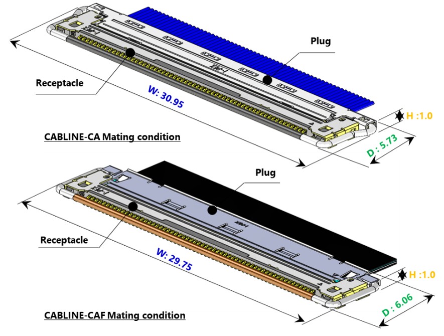
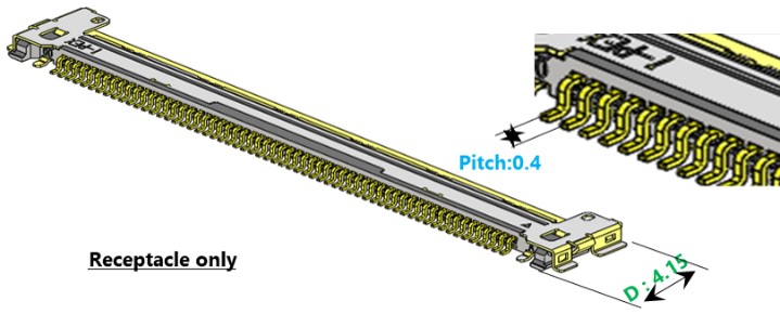
Features of CABLINE®-CA/CAF and CABLINE®-CA is a 0.4 mm pitch connector. Even with a 60-pin connector, the occupied area on the board is only 30.95 mm in width and 5.73 mm in depth, making it an ultra-compact, low-profile connector with a height of 1.0 mm.
Its features include a mechanical lock bar, which prevents incomplete mating or accidental disengagement. CABLINE®-CA is a connector designed for handling multiple micro-coaxial cables (mainly for transmitting differential signals or control signals). It has multiple ground connections and excellent high-frequency transmission characteristics. Additionally, CABLINE®-CAF is designed to accommodate FPCs into the plug shell and is compatible with the same CABLINE®-CA receptacle.
CABLINE®-CA/CAF Outline
Name |
CABLINE®-CA / CAF |
Mating Type |
Horizontal mating type |
Pitch |
0.4 mm |
Pin Count |
60 pin |
Height |
Mating condition : 1.00 mm |
Depth |
Mating condition : CA 5.73 mm
|
Width |
CA : 30.95 mm
|
Product Standard/TR |
CA : PRS-1968/TR-16023
|
4: Ultra-low-profile fiber array
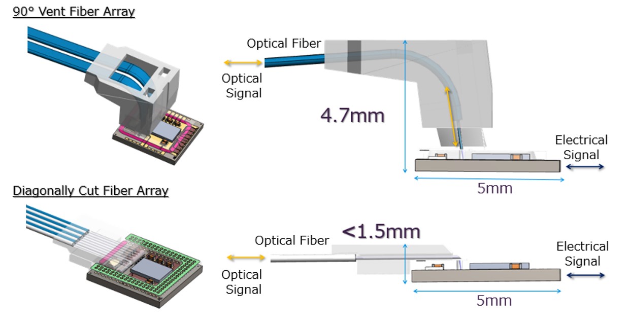
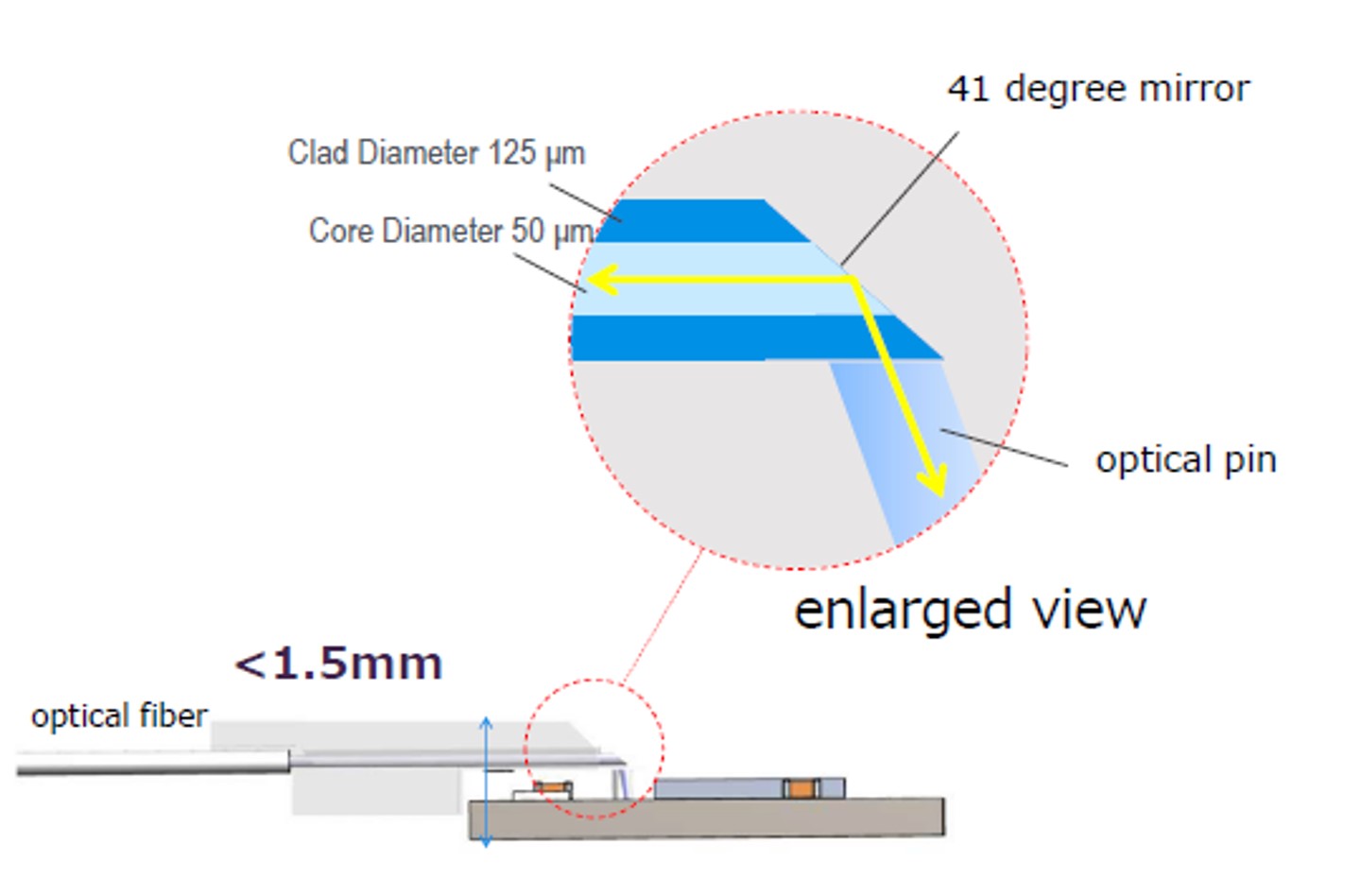
In the development of the LIGHTPASS®-EOB 100G ultra-thin optical module, it was necessary to adopt diagonally cut fibers instead of fibers bent at 90 degrees, to achieve a low-profile design. Here's an explanation of the purpose behind this decision and the details of the fiber array.
1) Reduced Height through Diagonally Cut Fiber Array
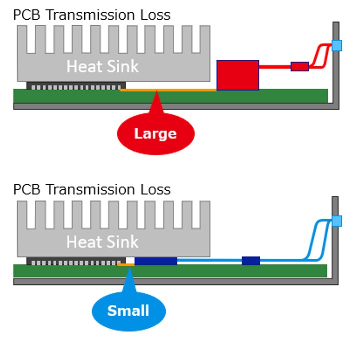
The implementation of a diagonally cut fiber array has enabled a low-profile design, allowing optical modules to be positioned closer to ASIC. This placement has led to a reduction in transmission losses in substrate wiring. Additionally, it allows for a common heat dissipation design with ASICs.
2) Diagonally Cut Fiber Array
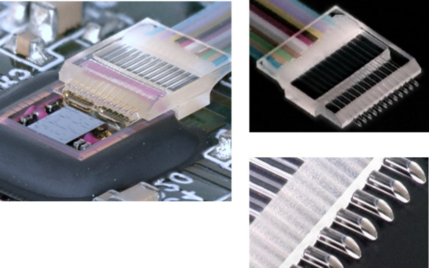
Ultra-thin Fiber Array Utilizing Reflection from Fiber End-face Mirrors.
We applied a fiber array where fibers aligned on V-groove glass were diagonally cut to serve as mirrors. This approach effectively reduced the height of the fiber block, achieving a module height of 2.3 mm.
3) Alignment Tolerance of Diagonally Cut Fiber Arrays
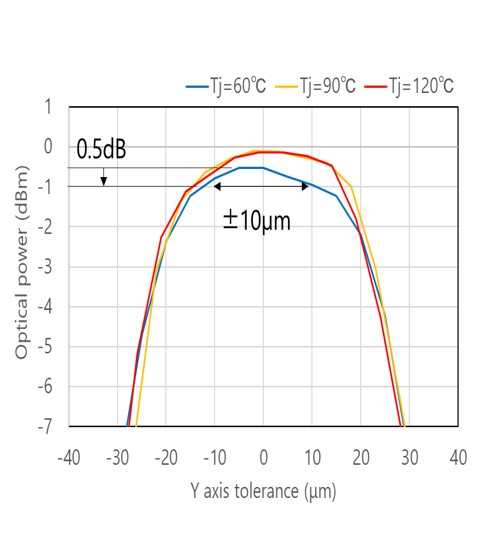
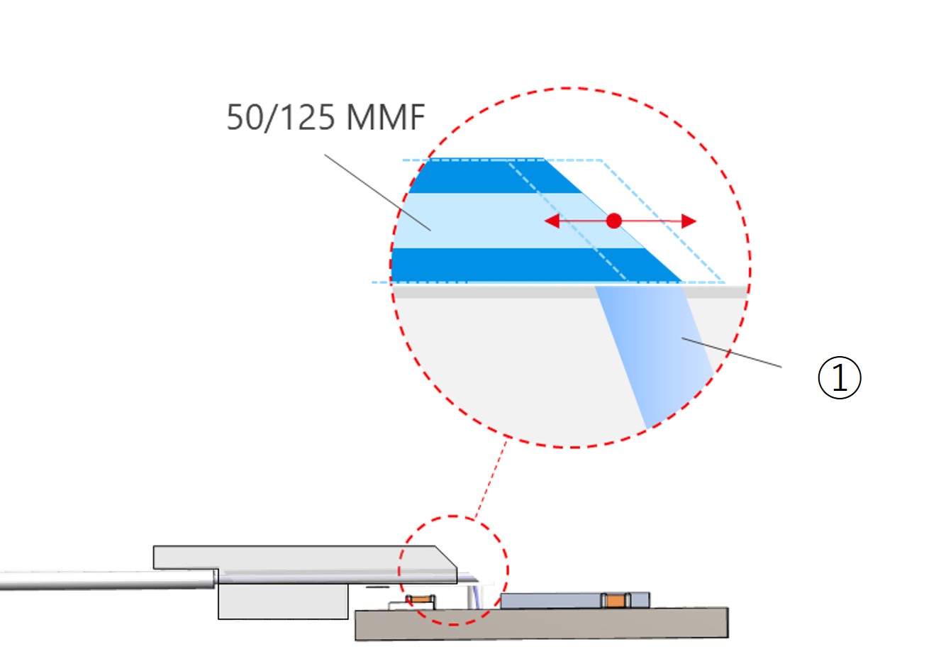
Fibers achieve alignment tolerances of ± 10 µm or greater over a wide temperature range.
To learn more about the LIGHTPASS product family, visit:
1: Ultra-thin optical module
2: Ultra-small optical transceiver engine
3: High-speed, low-profile, electrical connector
4: Ultra-low-profile fiber array
5: High heat dissipation module structure
6: Ultra-thin optical transceiver module evaluation results
Conclusion
