Discover On-Board Optical Module LIGHTPASS®-EOB 100G vol. 4
I-PEX has developed the LIGHTPASS®-EOB 100G on-board optical module. This article describes the detailed contents of that optical module.
To check out for previous chapter, visit the article of vol.3.
5: High heat dissipation module structure
The superior heat dissipation of LIGHTPASS® is achieved through a specific structural design that enables it to maintain a ΔTj-c of ≤ 15°C. This explanation will focus on how LIGHTPASS’s construction contributes to such effective thermal management.
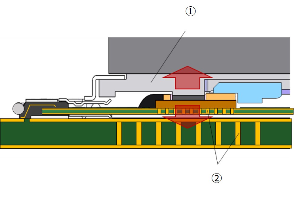
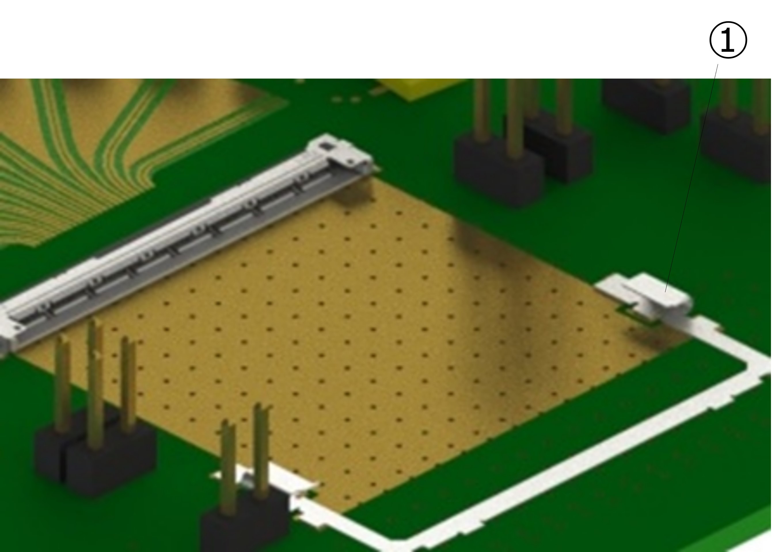
1) The heat dissipation structure
Efficient heat dissipation in the vertical direction is achieved through horizontal mating and a flat module design. To efficiently transfer heat to the heat sink located on the top, a heat spreader is integrated into the module structure. Utilizing anchor components to press the module onto the mounting substrate enhances heat dissipation efficiency towards the bottom of the module.
2) Heat dissipation specifications
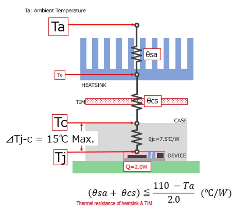
ΔTj-c≦15°C
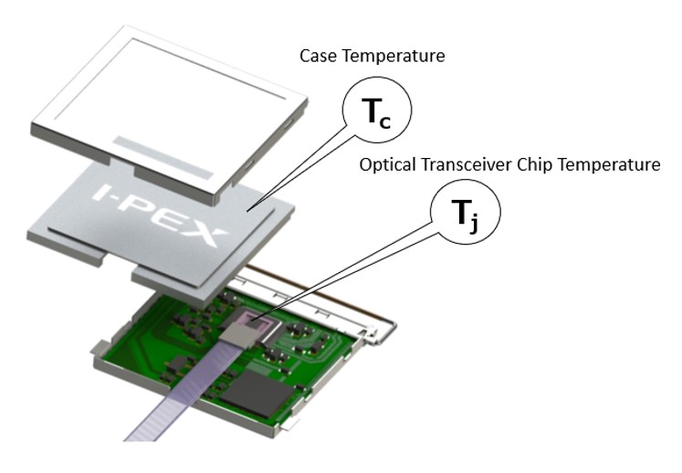
Efficient heat dissipation is optimized not only in the upward direction but also towards the downward direction, ensuring a temperature difference (ΔTj-c) ≤ 15℃ between the operating optical transceiver chip temperature (Tj) and the case temperature (Tc).
 |
 |
6: Optical transceiver module evaluation results
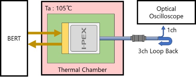
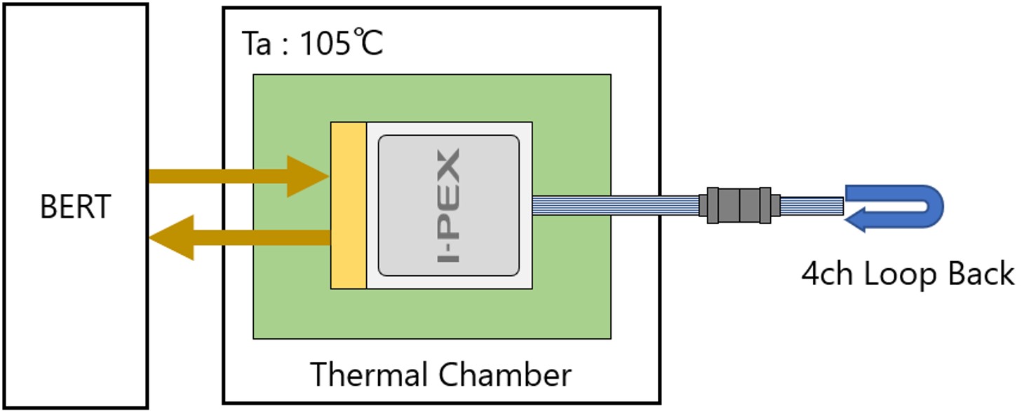
The optical module was placed in an environmental test chamber (Ta = 105°C), and 25.781 Gbps NRZ signals were applied to each lane from a BERT. In a loopback configuration where the optical signals were sent from the transmitter to the receiver side of the module, the operational state was evaluated for both heat dissipation and transmission performance.
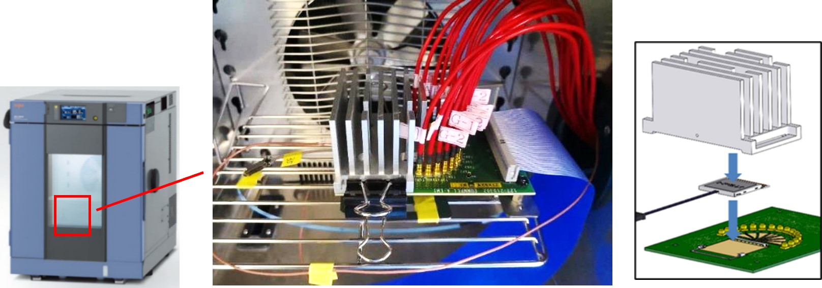
1) Heat Dissipation
Under high-temperature conditions (Ta=105°C), the heat dissipation performance allows the operation to remain below the chip's maximum operating temperature (Tj=120°C), ensuring it can be driven within specifications (ΔTj-c < 15°C).
Temp. [°C] |
Sample 1 |
Sample 2 |
Ta (Ambient Temp.) |
105.0 |
|
Tc (Case Temp.) |
106.4 |
106.3 |
Tj (Junction Temp.) |
117.9 |
118.3 |
(ΔTj-c < 15°C) |
11.5 |
12.0 |
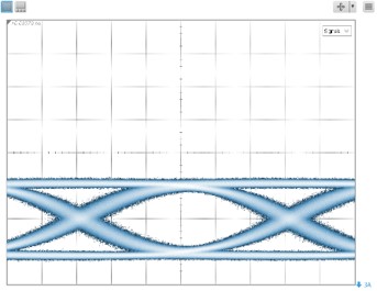
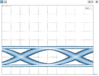
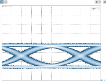
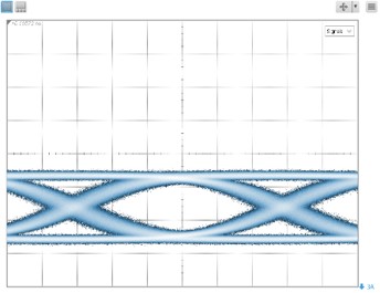
2) Tx Optical Output Waveform
Good eye opening was confirmed even in a high temperature environment (Ta = 105 °C).
Ta (Ambient Temp.) |
105°C |
Clock Rate |
25.781 Gbps |
PRBS |
31 |
LDD Current |
100 mA/ch |
Pre/Post Emphasis |
on |
 |
 |
 |
 |
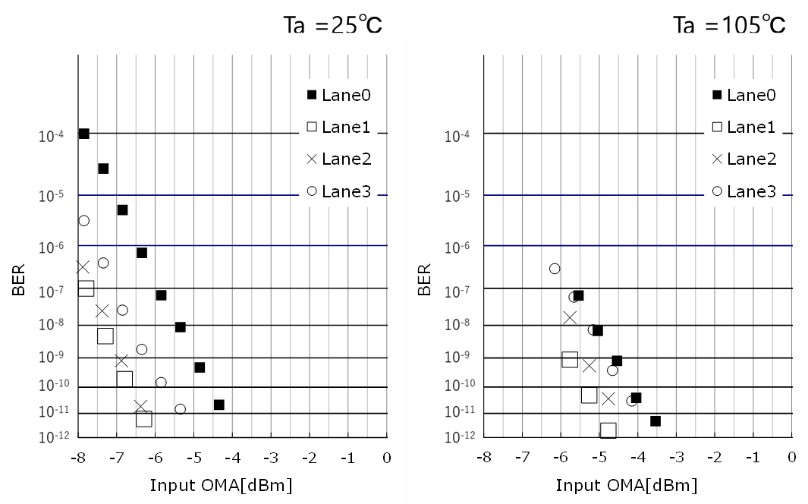
3) Rx Input Sensitivity
The optical signal from the reference optical module is attenuated through an attenuator until the BER (Bit Error Rate) is <10^-12, and the OMA (Optical Modulation Amplitude) = Input Sensitivity is measured. Even under high-temperature conditions (Ta=105°C), an input sensitivity with an OMA penalty of approximately 1dB is confirmed.
Ta (Ambient Temp.) |
105°C |
Clock Rate |
25.781 Gbps |
PRBS |
31 |
LDD Current |
100 mA/ch |
Pre/Post Emphasis |
on |

4) Result of Loopback BER
In the loopback configuration, BER < 1E-12 was verified for 25 Gbps per lane NRZ PRBS31 transmission across all temperature ranges.
Ta (Ambient Temp.) |
105°C |
Clock Rate |
25.781 Gbps |
PRBS |
31 |
LDD Current |
100 mA/ch |
Pre/Post Emphasis |
on |
Ta Ambient Temp. |
-40°C |
0°C |
25°C |
85°C |
105°C |
Lane 0 |
Error Free |
Error Free |
Error Free |
Error Free |
Error Free |
Lane 1 |
Error Free |
Error Free |
Error Free |
Error Free |
Error Free |
Lane 2 |
Error Free |
Error Free |
Error Free |
Error Free |
Error Free |
Lane 3 |
Error Free |
Error Free |
Error Free |
Error Free |
Error Free |
Conclusion
The LIGHTPASS®-EOB 100G, equipped with the ultra-compact optical transceiver chip developed as an ultra-thin optical transceiver module, demonstrates stable operation across a wide temperature range. Its excellent heat dissipation and transmission characteristics are proven. Error-free operation (BER < 1E-12) was confirmed even at a case temperature of 105°C. Leveraging these outstanding features, it can be effectively utilized in a wide range of markets and applications.
The proposed industries and devices
Medical: Endoscopes, Medical Robots
Telecommunication: Base Stations (Antenna Units, Inter-device Connections)
Data Information: Network Interface Cards (NIC)
Broadcasting: Professional Broadcasting Cameras
Aerospace: Satellite (Internal network), Avionics
We are applying this technology to drive the development of Four additional LIGHTPASS® products.
LIGHTPASS®-EOB 100G
LIGHTPASS®-EOB II 128G
LIGHTPASS®-EOS 100G
LIGHTPASS®-SP Q28
To learn more about the LIGHTPASS product family, visit:
1: Ultra-thin optical module
2: Ultra-small optical transceiver engine
3: High-speed, low-profile, electrical connector
4: Ultra-low-profile fiber array
5: High heat dissipation module structure
6: Ultra-thin optical transceiver module evaluation results
Conclusion
