Mating Direction of Connectors
There are various types of connectors, making it is necessary to find and select the most suitable connectors when developing new devices. Below is an introduction of the features related to the difference in the mating direction of small connectors used for internal connection of electronic devices.
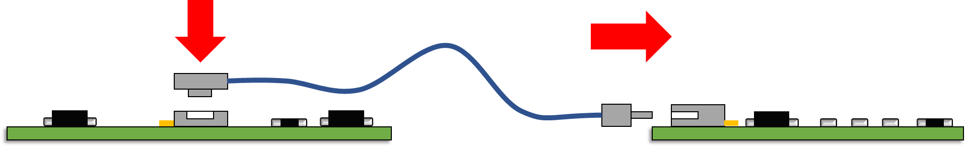
When connecting the signal of a PCB board to another board using a cable, an FFC or FPC, a connector that approaches vertically towards the surface of the board on which the connector is mounted and mates is called a vertical mating connector; while a connector that approaches horizontally is called a horizontal mating connector.
Connector Insertion Position
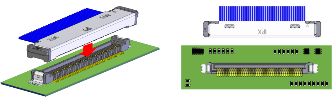
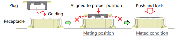
In the case of a connector in which a receptacle is mounted on a board and uses a plug to mate, the opening of the vertical connector receptacle faces upward. This makes it easy to visually check and locate the insertion position of the plug by looking down the board from above during the board assembly process.
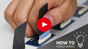
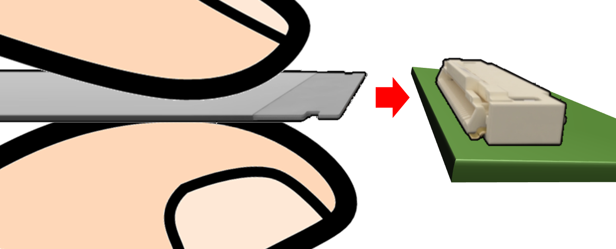
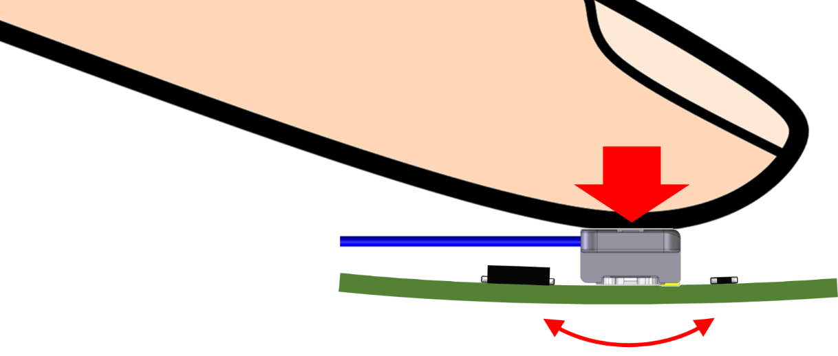
However, in the case of a board-to-board FPC connector, it may be difficult to visually align the plug to the correct insertion position for assembly, because the FPC covers the entire plug and blocks the view of the receptacle on the board.
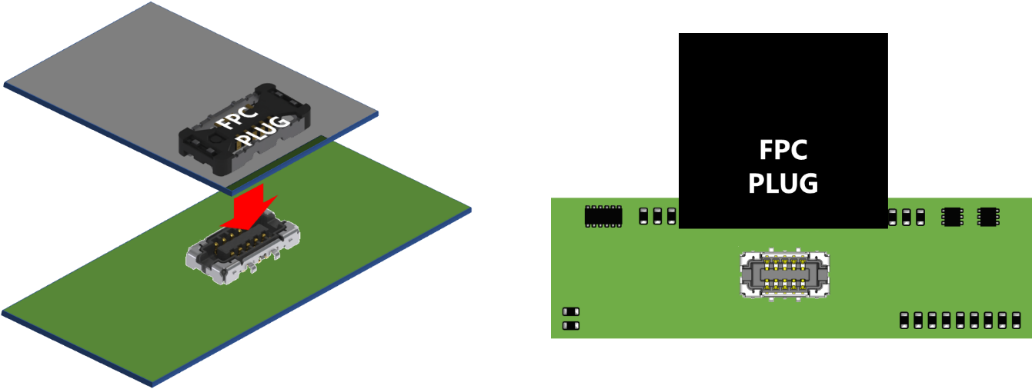
In such cases, it is important to have a guiding (alignment) function for connectors that allows a user to search for the correct insertion position using the sensation of fingertips while gently sliding the FPC plug onto the receptacle.
Placement on the Board and Clearance of Other Parts
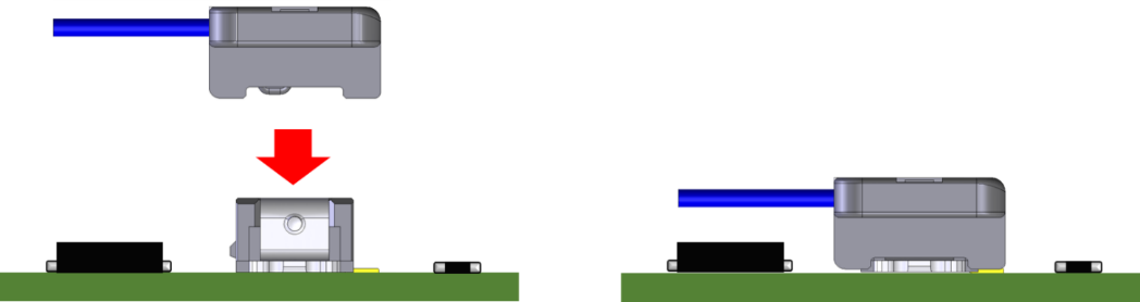
For the vertical mating connectors, the plug approaches the receptacle on the board from above and mates, so even if the connector is located in the middle of the board, it may not be difficult to mate the connectors. In addition, the clearance area around the connector is relatively narrow, so other components can be mounted around the connector. This gives more flexibility for designing the board than the horizontal mating type connectors.
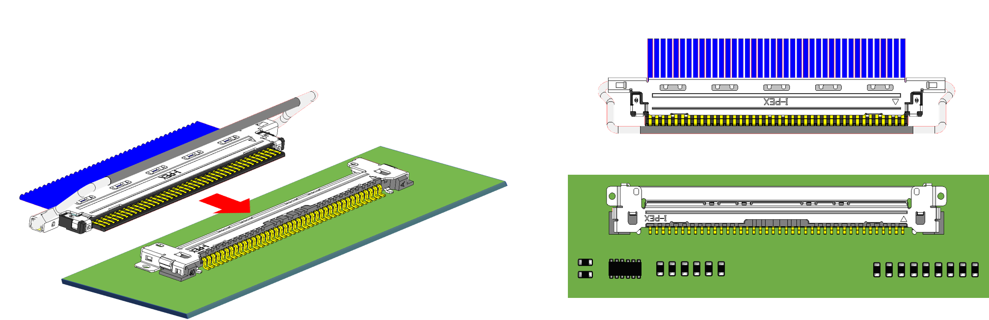
On the other hand, for horizontal mating connectors, the opening of the receptacle faces the side, so the plug moves parallel to the board surface to mate to the receptacle. Therefore, it requires a wider clearance area around the opening of the receptacle mounted on the board to make sure it does not get in the way during the plug mating process.
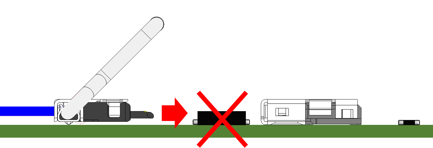
Also, if the low-profile horizontal mating connector is mounted in the middle of the board, the assembly process may become difficult as the fingers holding the FPC / FFC or plug hits the board during the mating process. When designing the board, it may be necessary to consider the assembly process, such as placing low-profile horizontal mating connectors on the edge of the board. (*Please refer to the Instruction Manual for each product for the correct handling of the connector.)
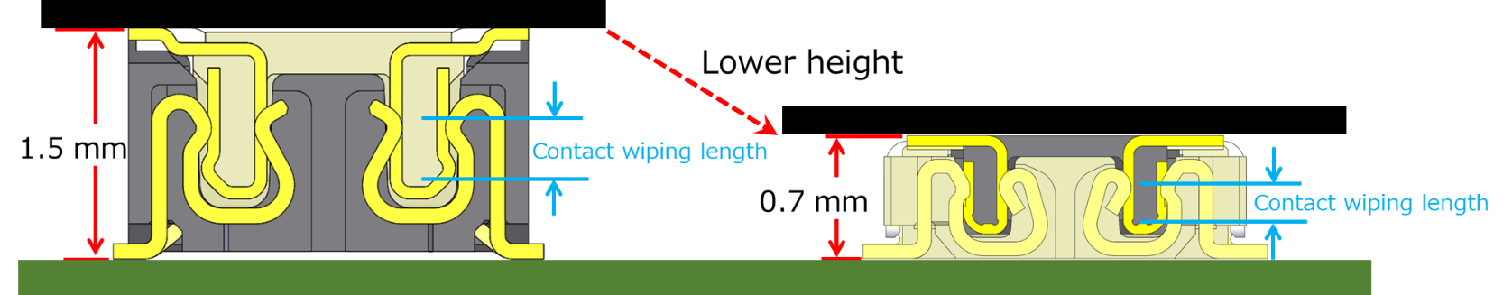
Connector Height Dimension and Contact Wiping Length
Because the contact wiping length is affected by the dimension of the mating direction, for vertical mating connectors, the contact wiping length is affected by the length in the vertical direction perpendicular to the board surface, that is, the connector height dimension. In portable high-performance devices, such as smartphones and tablets, components are mounted at a high density in narrow and limited spaces. In such devices, it is required that the size of the components to be small and low-profile, but it may be difficult to keep the contact wiping length when the vertical mating connector height is lowered.
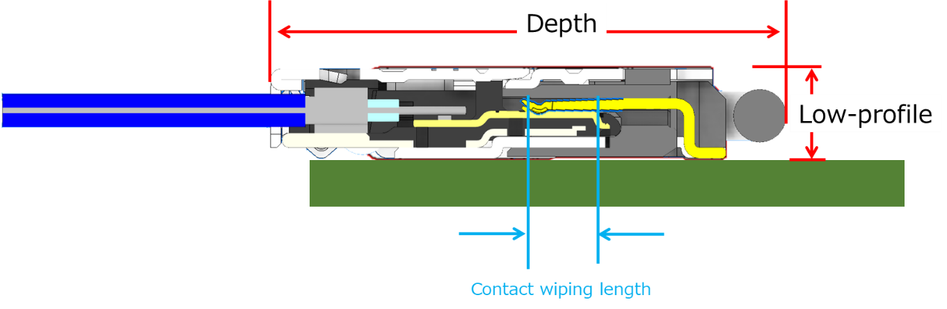
For horizontal mating connectors, the contact wiping length is affected by the length in the horizontal direction parallel to the board surface, that is, the depth dimension of the connector. Therefore, compared to the vertical mating connectors, it can be easier to consider lowering the height of the horizontal mating connectors while keeping the contact wiping length.
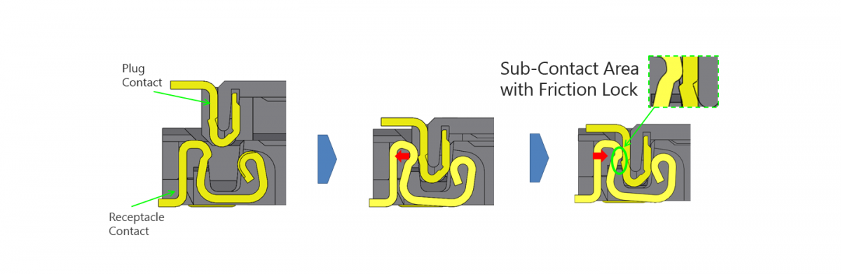
Mating Retention of Low-profile Connectors
A shorter contact wiping length means that the required range of the mating position’s tolerance to ensure contact between the contacts is narrower. So, there may be a higher chance of losing contact with the contacts, for example, if the device is dropped and the mating position is moved. One of the ways to improve the contact reliability of the contacts is to strengthen the mating retention force between the plug and the receptacle by using a locking mechanism such as a friction or mechanical lock.
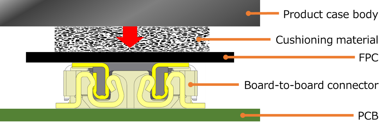
In addition, one of the methods to supplement the mating retention force of the vertical mating connector is by attaching an appropriate cushioning material above of the connector. As a result, the cushion material presses the connector appropriately and keeps the connector mating position in place when the product case body is attached.
This method can be considered when developing small portable devices, for example, that may be dropped while being carried. (*However, please be careful of applying excessive pressure to the connector as it may cause damage.)
Effect of Insertion Force
Since the vertical mating connector is mated by inserting the plug toward the board, a vertical mating connector with a high insertion force may apply excessive pressure to the board during the mating process. Therefore, when assembling a board that is not suitable for applying pressure, such as a panel integrated module board, it may be necessary to take measures such as selecting a vertical mating connector with a low insertion force, preparing the assembly environment that does not cause deforming the board while assembly, or selecting a horizontal mating connector.
Summary of Features of Vertical Mating/Horizontal Mating Connector
| Vertical mating connector | Horizontal mating connector |
| Compared to the horizontal mating connector, the clearance area around the connector is narrower and has more flexibility for designing the board. | Dead space on the board is likely to be created, as the clearance area near the opening becomes relatively wider. |
| Even if the connector is mounted in the middle of the board, there would be no significant effect on the mating process. | The mating process of the connector mounted in the middle of the board may become difficult, in the case of a low-profile, small connector. |
| It may be difficult to lower the height of the connector while keeping the contact wiping length. | Compared to vertical mating connectors, it is relatively easy to lower the height of the connector while keeping the contact wiping length. |
| Excessive pressure may be applied to the board when assembling a high insertion force connector. | Pressure applied to the board during assembly is likely to be smaller than assembling a vertically mating connector. |
I-PEX Connector Lineup Introduction:
I-PEX has a connector series that supports both horizontal and vertical mating, so the suitable mating direction can be selected according to various applications and design conditions. For example, a horizontal mating connector can be used on the panel board where a narrow connector is required, and a vertical mating connector can be used on the board where high-density mounting is required in the middle of the board.
Micro-coaxial Connectors
- 0.4 mm pitch, micro-coaxial connector with EMC shielding cover and mechanical lock
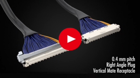
Horizontal mating type: CABLINE®-CA II
Vertical mating type: CABLINE®-UM
- 0.4 mm pitch, micro-coaxial connector
Horizontal mating type: CABLINE®-CA
Vertical mating type: CABLINE®-SS
- 0.5 mm pitch, micro-coaxial connector
Horizontal mating type: CABLINE®-VS
Vertical mating type: FPL™ series
FPC/FFC Connectors
- 0.5 mm pitch, with grounding and auto-locking, FPC/FFC connector
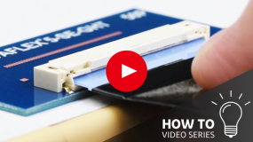
Horizontal mating type: EVAFLEX® 5-SE-G HT
Vertical mating type: EVAFLEX® 5-SE-G VT
- 0.5 mm pitch, with auto-locking, FPC/FFC connector
Horizontal mating type: EVAFLEX® 5-SE
Vertical mating type: EVAFLEX® 5-SE VT