I-PEX's unique countermeasure to potential issues caused by closing actuator without FPC inserted
Contents
Background
Each connector manufacturer assumes how connectors are used at the customer's site and establishes an operation manual and rules for use by the customer. Even with careful handling, there are many cases of poor connection or incomplete mating at the site where the connector is used. Among them "Empty-Closure" is widely known as a common occurrence for FFC/FPC connectors in manufacturing and assembly sites. Empty closure means operating the actuator without inserting the FPC into the connector, which can cause connector damage or incomplete mating when the FPC is subsequently inserted. There are various situations that can be anticipated at the customer's manufacturing site, and there are many cases where the actuator is locked with no FPC inserted due to unfamiliar operation or blind mating. It would be good if it could be detected during the inspection process at the manufacturing site, but there may be cases where the final product is delivered with a defect caused by empty closure. In such cases, deformed connectors or FPCs may cause problems in the market.
This white paper introduces the "empty closure" issue, using I-PEX's MINIFLEX® series as an example, and how it is addressed, as well as the design know-how gained through analysis and calculation to ensure that the connector will function even if an empty closure occurs.
Assignment
As a premise, the mission of a connector is to provide a stable connection of signals and currents in any environment where all electronics-related devices operate. For example, we believe that even if an actuator is opened and closed several times with no FPC inserted, contact reliability must not be compromised. So, what kind of changes and problems will occur if the actuator of the connector is actually closed without an FPC inserted.
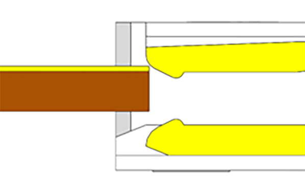
If the actuator is closed with no FPC inserted, the shape of the contacts in the connector will be deformed. This causes a change in the gap between the contacts, which is the contact point with the FPC. As a result, the FPC is likely to be improperly inserted, resulting in non-conduction or poor connection. As a typical example, if an FPC is inserted with a deformed contact (narrow gap), buckling (Note 1: stubbing) may occur (see Figure 1). If buckling occurs and a poor connection occurs, the connector will not function.
Note 1: The tip of the contact hits the FPC, causing deformation and failure (Figure 1: see figure on the right).
 |
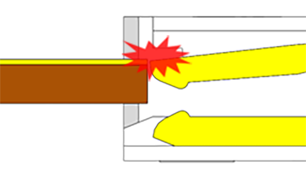 |
| Left: Initial state | Right: Buckling state |
| Figure 1: Deformation of contacts after empty closing, causing interference with FPC and resulting in failure | |
Countermeasures/Solutions
I-PEX FPC/FFC connectors (MINIFLEX®) are designed to function as normal connectors even in the event of empty-closure occurs. Behind this ingenuity is a connector design based on three know-how and three verification results, which are described in detail below.
Know-how ①
- Tolerance analysis verifies the allowable plastic deformation of the contact area due to empty closure.
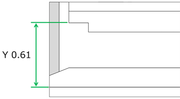
Buckling does not occur during FPC insertion unless the contact tip (see Figure 2), which is deformed due to the empty closure, drops down from the housing rib and protrudes. Tolerance analysis is performed using the root sum of squares (see Table 1) to verify how much plastic deformation of the contact can be tolerated.
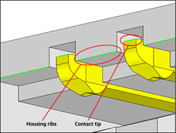
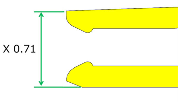
The amount of housing rib and contact tip wrap is calculated from the dimensional tolerances of the individual parts of the housing and contact. The resulting worst value (Min value) is the allowable amount of plastic deformation in the contact.
 |
 |
| Contact | Housing |
| X (contact) | 0.71 ± tolerance A |
| Y (housing) | 0.61 ± tolerance B |
|
(housing rib - contact tip) Lapping amount |
X - Y = 0.71-0.61 ± √(A^2 + B^2) = 0.10 ± C |
| Worst value (Min value) | 0.10 - C |

Know-how ➁
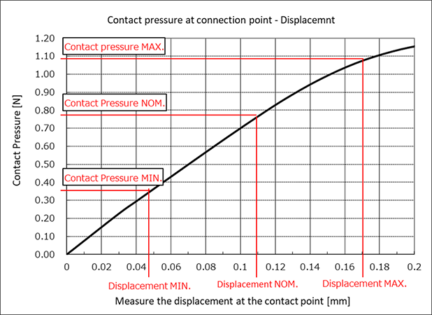
- Verified the relationship between displacement and contact pressure (P-delta curve) at the contact point by analysis.
After modeling the contact shape that meets the size and space requirements from the customer, the relationship between the displacement of the contact and the contact pressure (P-delta curve) is graphed by analysis (Figure 4: black line). In the graph, the range of displacement of the contact analyzed by tolerance analysis based on the dimensional tolerance of the individual parts is plotted to check the contact pressure (Figure 4: red line). If the minimum contact pressure does not meet the I-PEX standard, increase the displacement of the contact point or consider a shape that increases the slope of the P-delta curve.
Know-how ③
- Verified the amount of plastic deformation due to "empty closure" in the analysis.
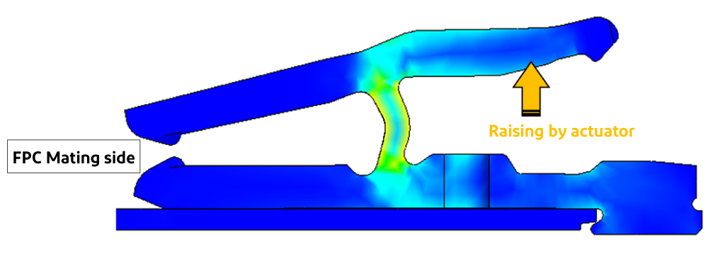
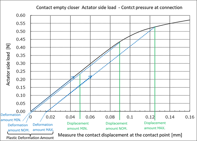
The tolerance range used for the displacement is calculated using the GAP dimensions of the actuator side of the contact (Fig. 5: yellow arrow) and the actuator cam dimensions. The amount of plastic deformation due to the empty closure of the contact shape determined by ② is confirmed by analysis. Confirm the amount of plastic deformation at the contact based on the relationship between the load on the actuator side contact and the amount of contact displacement. (See Figure 6)
If the result exceeds the allowable amount of plastic deformation determined in know-how:①, the contact may protrude out of the housing and cause stubbing if it is actually closed empty, so the design should be redesigned.
The above-mentioned analysis and analyzation are conducted using I-PEX's proprietary know-how and technological capabilities to determine the design of connectors that can support empty closure. If the displacement of the contact is set too large and flexible in an attempt to follow the FPC and maintain contact pressure and reliability, the deformed contact tip may protrude beyond the housing ribs, leading to stubbing, as in the previous example, when the empty closure occurs, resulting in a poor connection. This will increase the possibility of stubbing and connection failure.
On the other hand, if the displacement of the contact is set too small in order to accommodate empty closure, the contact displacement will be small even when the actuator is opened and closed, and the proper mating state will not be maintained, resulting in reduced contact reliability and possible non-conduction or failure. After confirming the above items (1) to (3) (no particular order), we will complete the design of connectors with measures to prevent empty closure. After that, the following three items are established and verified in the connector manufacturing process.
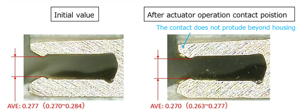
1: Change in Contact Gap after multiple cycles of empty closing (actuator operation with no FPC Inserted) is minimal.
Number of actuator operations (horizontal axis)/contact GAP (vertical axis)

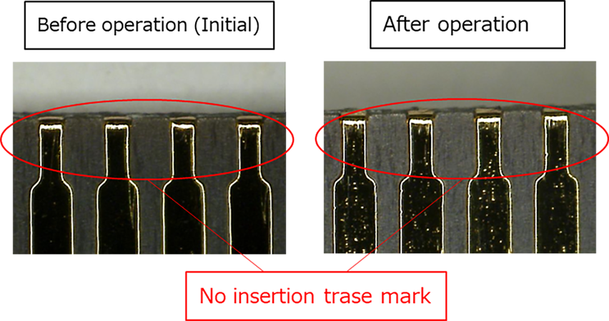
2: Change in FPC Insertion force after multiple cycles of empty closing (actuator operation with no FPC Inserted) is minimal.
Number of actuator operations (horizontal axis)/insertion force (vertical axis)

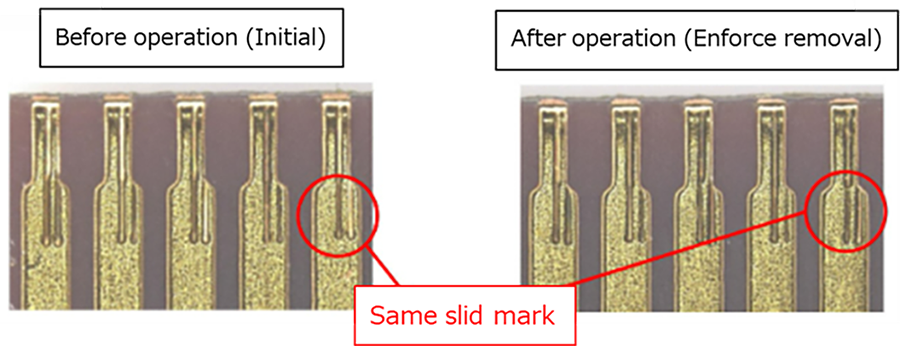
3: Change in FPC retention force after multiple cycles of empty closing (actuator operation with no FPC Inserted) is minimal.
Number of actuator operations (horizontal axis) / FPC holding force (vertical axis)

Consequence
“Empty closer” = Even if an actuator operation event occurs with no FPC inserted, the connector will still function as a connector, thereby reducing non-conductivity and connection failures. In fact, this empty closure countermeasure is also effective in test operations involving multiple open/close operations at the manufacturing site, making it a useful solution for many of our customers.
Summary
As described above, each design process requires highly sophisticated I-PEX proprietary design know-how, and we are constantly evolving and refining our core technologies. In addition, connector manufacturing sites are focusing on how to ensure quality and produce superior products by establishing precise criteria.
MINIFLEX® 5-BFN II Product page: https://www.i-pex.com/zh-tw/product/miniflex-5-bfn-II
